One of my hobbies is to write small programs which generate graphics and animations. In order to be able to see the results of my work in the “real world” I’ve built a computer-controlled plotting machine.
There were/are couple of commercial solutions available, but they are either too expensive, too small, or both.
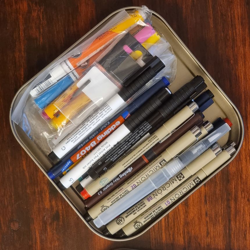
I’ve tried to build something small enough so it fits on my desk, while still having working area of at least DIN A2 size. It was also important to me that plotter would handle different tools: such as pens, pencils, brushes, and whatever else I might come up with.
Mechanics
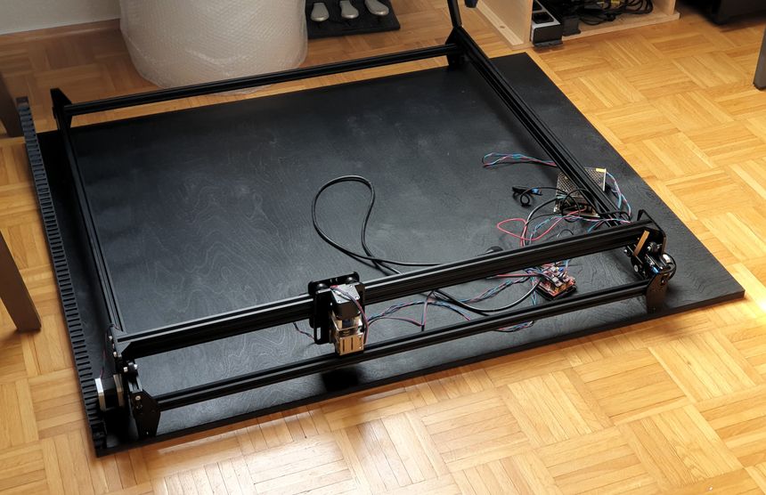
The project’s mechanics part is straightforward. It is based on Acro from OpenBuilds. I’ve sourced all the required components online and made some modifications to the frame, namely:
- Added the Z-axis
- Built several custom tool mounts for the Z-head
- Cut the aluminum extrusion so that inner surface size is roughly 50 cm wide and 70 cm deep
- Instead of plastic tubing, which Acro is using to route cables, I’ve opted for cable chains
The major pain point was to build a universal tool holder, which would tightly clamp any drawing tool with a diameter range of ⌀ 4mm to ⌀ 25mm, while having an adjustable pressure to the drawing surface.
I think I did close to a dozen iterations with different designs until finally ditching the idea of having the universal holder. Instead, I’ve settled on building three different holders and laser cutting the adapter plate to quickly change between them.
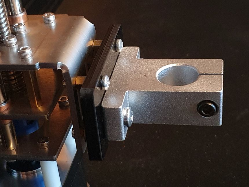
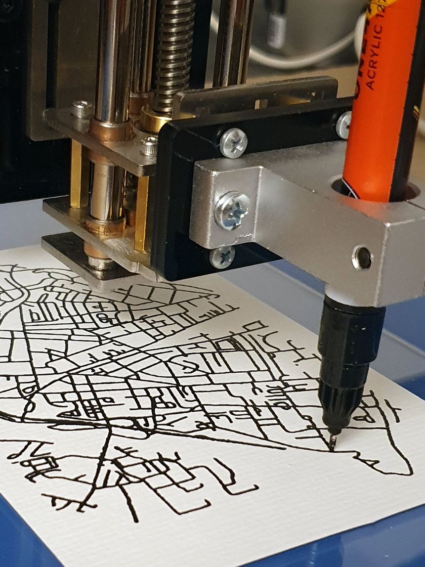
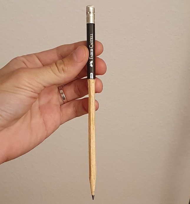
Turns out, sometimes it’s easier to adapt the tool to the holder, than the other way around:
Software
To plot something, usually, at least two pieces of software are needed:
- The one which will generate G-Code from the source vector file. That functionality is usually included with specialized CAD and CAM software
- The software which interfaces the controller in the machine — it’s a separate program which sets various settings, loads G-Code files and streams the commands providing movement controls
There is some software available for both categories, but the CNC-plotter is not the most popular type of CNC machines out there — majority of this software is complicated, cumbersome and has a lot of unnecessary features.
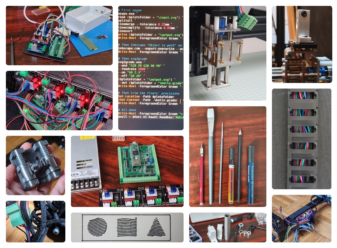
To streamline the G-Code generation I wrote a small application which generates G-Code from drag-n-dropped .svg file. All of the underlying complexity is hidden in a separate configuration file — that way I can set everything up once and forget about it.
For the “G-Code sender” part — I’ve bootstrapped on the existing software and wrote an alternative front-end which features only the controls I need.
I’ve created two versions of it: one designed to run on a small touchscreen connected to Raspberry Pi, and one for the bigger display of a desktop computer.
Electronics and firmware
Mechanics, electonics and controller’s firmware are tightly connected in this project — changing one would affect the others.
In the beginning, I was using Arduino with grbl as the firmware. It’s super-easy to setup and get going but has it’s own problems.
Grbl has a limitation on maximum step-frequency of ≈30 kHz. The (theoretical) maximum speed of plotters’ travel is calculated as
Trying to push the steppers to the maximum speed, until they stall, I’ve found the real maximum speed to be around 2500 mm/min. That’s a bit limiting, as I want to save as much time as possible on the pen travel.
On top of that, the Arduino is somewhat underpowered controller, lacking a lot of fancy features which might come handy later, such as network and SD-card support.
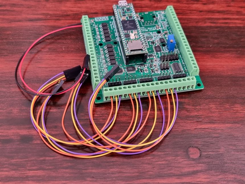
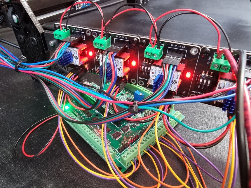
While researching for an inexpensive but powerful enough solution I stumbled upon the grblHAL project, which is basically Grbl with ARM processor support. I bought a breakout board which is using Teensy 4.1 as the main controller and it turned out perfect for my needs. Way higher step rate, which means faster travel speeds, Ethernet and SD-card support, up to five axes (or three axes with two of them being ganged), support for I2C keypad and more. All of that for less than €60, as I’ve had a Teensy laying around already.
A mild inconvenience with a new board was a fact that it doesn’t have pin headers for seating a StepStick-style stepper driver. I think the board is designed with “professional” big, full-metal chassis drivers in mind. They might be a bit more convenient, because of their screw terminals and chassis, which acts as a heat sink; they are more expensive though and way more bulky, which is important because I was trying to keep the plotters’ footprint low.
Other modifications
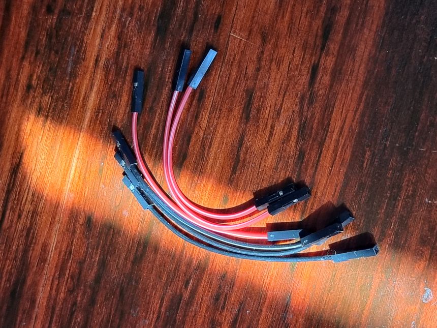
So, with a new controller board came almost the full overhaul of the electronics — new screw terminals on the controller board required breakout boards for each driver. I’ve tried to do everything in a neat(er) way: I’ve crimped all of the connectors myself in order to have the exact-length cables. I’ve also quickly modelled and 3D-printed a small baseboard to hold the drivers’ breakouts and a mount for the newly bought power supply, as well as made other small improvements.
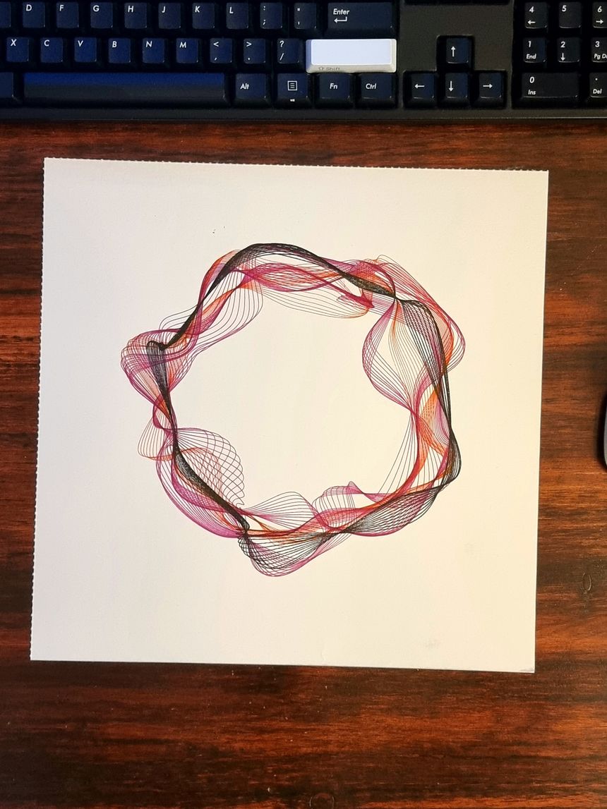
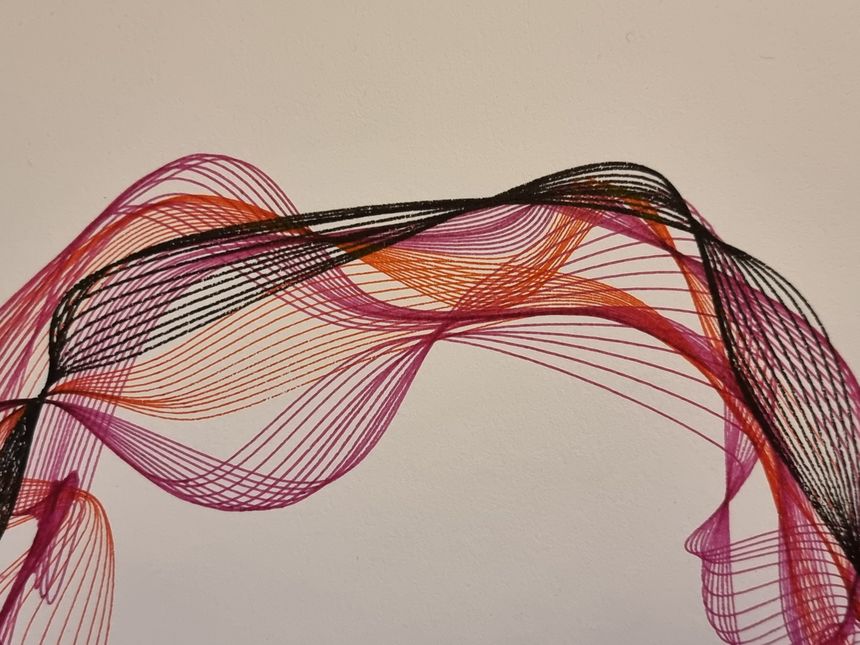
At this stage I was really happy with my plotter and drew some new pictures.
Trying to minimize the time fiddling around before plotting — I’ve also added the Hall-effect switches for automatic homing and built a simple Z-leveling solution, using the regular keyboard switch:
With those two I can just press some buttons and have a plotter to return to exactly the same position every time — that way I can switch the pens to different colors for each layer in the image and still have it aligned perfectly:
Afterword
There are a lot of things which I didn’t mention in the article, hundreds of additional photos and videos. Still, I hope it gives a glimpse at the process of building my plotter.
There is still more to do (as always), but I’m pretty happy on how the plotter turned out and how it sits today.
I’m planning to add more pictures from time to time to the result page, but that’s it for now. Check out my other projects and as always, feel free to reach out to vn@vnvn.me if you want to chat about this project or anything else.